2021-07-26
Digital simulation using finite element analysis method
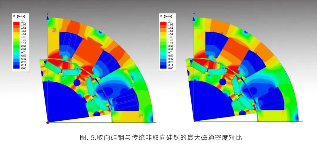
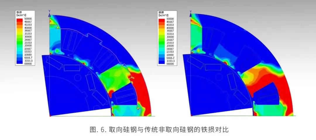
In the electromagnetic simulation, we measured the magnetic flux density, iron loss, output torque and efficiency map. The simulation results are shown in Fig. 5 and Fig. 6. It can be seen from the figure that under the same current excitation, two different cores show different results. In Fig. 5, the range of go teeth above 1.96t is large. According to the experimental results in Fig. 1, go silicon steel can reach saturation faster. Go steel plate can reach the turning point below 100A / m, while NGO steel plate needs to reach the turning point at about 200A / m. The maximum magnetic flux density of go steel is higher. As shown in Figure 6, the maximum iron loss point of go type is low under the same excitation condition for the two core models. The iron loss of NGO silicon steel is larger than 4.66w/m3, and it is mainly concentrated in the stator yoke. The results show that the iron core of go motor is 12.1% lower than that of conventional motor.
Of which:
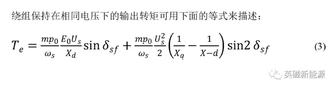
Te: represents output torque;
m: Represents the number of phases, equal to 3;
P0: represents the number of poles, equal to 8;
ωs: Represents the mechanical speed of the rotor divided by the number of poles;
E0: represents back EMF;
U: Represents the winding voltage;
Xd: represents d-axis reactance;
Xq: represents q-axis reactance;
δS f: represents the angle between the permanent magnet connecting rod and the stator connecting rod.
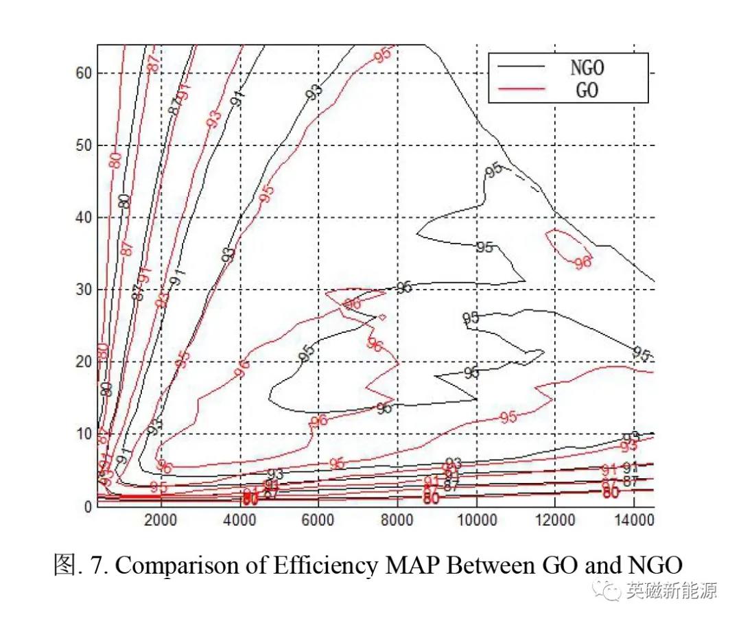
Go silicon steel has higher magnetostriction than NGO silicon steel. From the magnetostriction mechanism of ferromagnetic materials, the movement of domain wall and the rotation of magnetic moment are the reasons for magnetostriction. The magnetostriction of go silicon steel sheet not only has a strong nonlinear relationship with the magnetic field, but also is affected by various complex factors such as system temperature and prestress conditions, which means that the equivalent magnetostrictive force cannot be solved at the same time with the magnetic flux density. Therefore, we need to use the weak coupling model to meet the requirements. The weak coupling model of magnetic field and structural field of ferromagnetic materials is solved by finite element method as follows:

Where: s is the magnetic field stiffness matrix; A is the magnetic potential loss to be determined in the vector; J is the current density in the vector; K is the mechanical stiffness matrix; U is the displacement deformation in the vector; F is the stress vector of magnetic material (including mechanical force, electromagnetic force and equivalent magnetostrictive force); Figure 7 shows the comparison of the efficiency map of the two motors under two working conditions. The iron loss of go motor is lower than that of traditional motor, especially in the high efficiency range, which shows that go motor has obvious advantages in reducing iron loss. From the comparison, we observe that the maximum power increases from 95.2% to 96.8%, about 1.6%. At the same time, the high efficiency range of all working areas of the motor is also improved.
The next issue will continue to introduce the results of finite element analysis of the new motor and the prototype manufacturing process and conclusions of the new motor. Thank you for watching!