2021-07-15
Design of oriented silicon steel stator combined with non oriented silicon steel
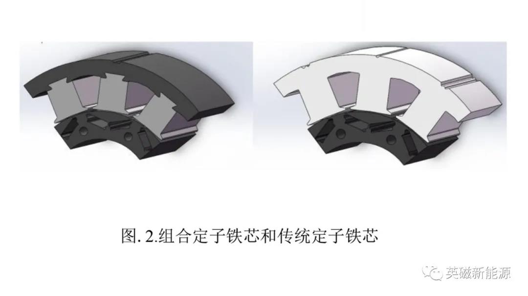
In order to prevent the go silicon steel from deviating from the rolling direction by more than 30 ° in the rotating magnetic field, we set that the stator core is composed of go teeth and NGO yoke ring, as shown in Figure 2. The stator yoke adopts NGO silicon steel and the teeth adopt go silicon steel. The thickness of the two silicon steels is the same, both of which are 0.3mm. In order to ensure that it is always in the rotating magnetic field, go silicon steel always keeps the magnetic flux density in the rolling direction.
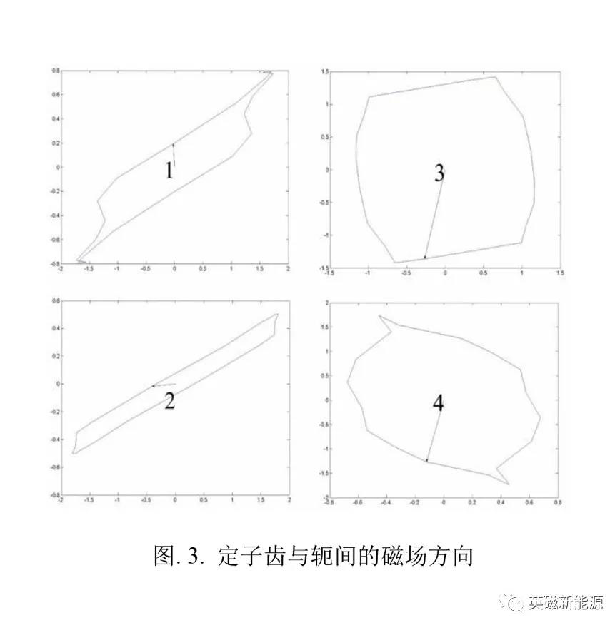
We also simulated four points in the stator core. In one cycle of the mechanical angle, we simulate the magnetic density of the stator core. Point 1 is at the top of the stator teeth, point 2 is at the end of the stator teeth, point 3 is in the center of the stator yoke, and point 4 is outside the stator yoke. In addition, we decompose the magnetic density of the stator core in one cycle, as shown in Fig. 3. It can be seen from the figure that in the rotating magnetic field, the teeth of the stator are always subject to a magnetic field in the opposite direction, while the yoke is affected by the rotating magnetic field. Therefore, go silicon steel can be used as the iron core of stator teeth in motors.
Digital simulation using finite element analysis method
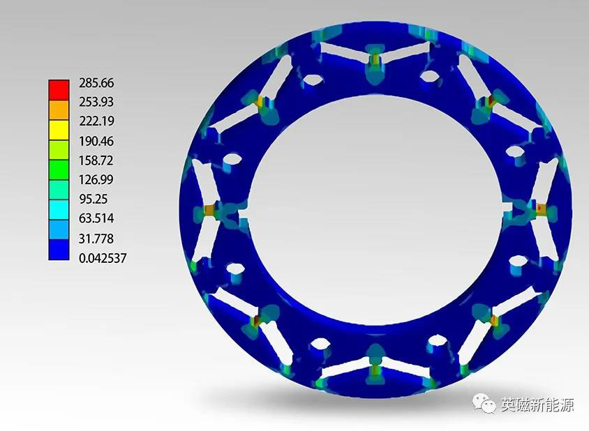
The prototype of the project is a motor with rated / peak power of 16 / 32kw, maximum speed of 14500 rpm and liquid cooling system. We use the finite element method to model the topology. The rotor adopts segmented inclined pole, and the rotor silicon steel sheet is also b30ahv1500. Through centrifugal force simulation, as shown in Figure 4, At the limit speed of 17400rpm (maximum speed of 120%), through von Mises criterion, the rotor core stress is 285.66mpa and the safety factor is 1.3233, which meets the yield limit of the material. In addition, we also carried out modal simulation and thermal simulation. In the simulation process, considering the gap caused by the splicing of the two, 10% allowance is reserved.
The next issue will continue to introduce the results of finite element analysis of the new motor. Thank you for watching!